OSI MODEL LAYER 1
OSI LAYER MODEL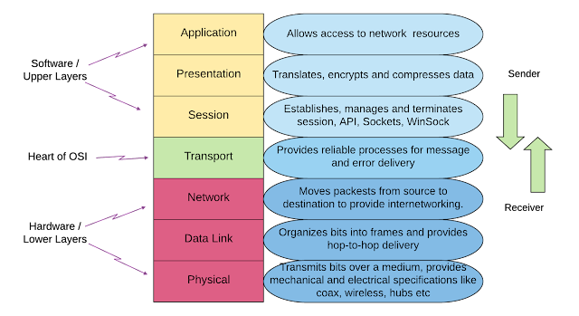
Physical Layer
Data Link Layer
Transport Layer
Network Layer
Session Layer
Presentation Layer
Application Layer
OSI Layer Model For Student :
This OSI Layer Model discussion will begin with a Cobham
Collage Campus network connecting to their private network's Online Learning
System Server via their home network (public IP address) (Private IP Address).
Assume that the Cobham College Campus network is attempting to upload a file to
the Cobham College Online Learning System. Let's start with the Application
Layer, where data transit services such as SMTP, POP3, and others are supplied
to the file that a Cobham Collage student wishes to submit into the Cobham
Collage Online Learning System platform. The data is transported using the file
transfer protocol (FTP) in this situation. On the Presentation Layer, the file
will be converted to binary format, and file compression will begin in order to
reduce the file's size. A 7MB file, will be compressed down to 3MB, allowing
the content to be transferred even faster. Finally, it will encrypt the file
delivered by the sender using SSL or another security protocol for data
security concerns. The data will subsequently be transmitted to the session
layer, which will manage the communication session without interfering with the
communicating systems' ability to communicate. The packet data unit for these
three processes is data, which will be broken down into segments in the next
phase. This transit layer is where the segmentation begins. Each segment
contains the source and destination port numbers, as well as the sequence
number. The port number's purpose is to get the data on the appropriate track,
whereas the sequence number's goal is to reorder the out-of-order segments.
Furthermore, error control is an important part of this layer since it
determines whether the segments have arrived and, if not, re-sends them. The
two protocols employed in this operation are TCP and UDP. In our instance, TCP
will be used to send the file since it assures that each data packet is
transmitted and receives a message indicating whether or not the data has been
received. Why didn't we utilise UDP instead of TCP? Because UDP is primarily
used for video streaming, it does not reply to whether or not the data has been
reached. The network layer is the following layer, and it's here that the
crucial parts of our data trip are influenced by the scenario due to
communication between public and private IP addresses. This layer is
responsible for delivering packets (PDU) from the original source (Sender) to
the final destination (Receiver). Logical addressing, which allocates an IPv4
destination to each segment, and routing, which handles packet delivery based
on the IP address and subnet mask, are two procedures involved in this layer. Because
of the public to private IP address, the routing will be different in this
situation, with the sender (Public IP address) transmitting the data to the Cobham Collage Campus network main router (Public IP address), and then another routing within the Cobham Collage Private IP Address to transfer the data to the requested host. The data link
layer is the next layer, where the hardware's MAC address is appended to the
packet and the frame is created. The objective of MAC is to maintain track of
data packets as they go over a shared channel from one Network Interface Card
(NIC) to another (Hop-to-Hop Delivery). Finally, the physical layer is in
charge of moving bits from one layer to the next. In addition, the physical
layer converts binary into a signal that can be transmitted over a medium. In
this scenario, wireless and wired media are used.
7.Application Layer
Students will use the user interface (UI) to access the
system via application programmes or the website. Data will be sent when a
student requests access to the system. The application layer uses the https
protocol to deliver commands, and this tier (layer 7) will place a header field
with information and pass the data to the Presentation layer (layer 6).
6.Presentation Layer
The data will be transformed to a binary format that can be
understood by machines. Encryption and compression will also be provided by
this layer. This layer places header information and then passes the new data
to the Session Layer in this example (layer 5). FTP, SSL, and other protocols
are used.
5.Session Layer
To handle the sessions, a header will be appended to the
data in this layer. This layer is in charge of making it easier to create,
handle, and terminate connections between nodes. This layer will handle the
data flow after adding headers and will pass the data to the Transport layer
(layer 4).
4.Transport Layer
Data is changed or disintegrated into segments, which are
then reassembled at the server via the transport layer. Later, each of the
fragmented segments is transferred to the Network Layer (layer 3), where the
source and destination ports are also defined. Flow control, fragmentation,
port assignment, and dependability are all handled by this layer. TCP is the
most well-known transport layer.
3.Network Layer
This layer provides internet addresses and specifies the
data's path of transmission, which is where routing takes place. The source and
destination IP addresses will be assigned to the segments, and the segments
will form packets. After that, the packets will be sent to the Data Link layer
(layer 2).
2.Data Link Layer
This layer will add a layer 2 header to guarantee that the
data isn't corrupted before passing the new data, frame to the Physical layer
(layer 1) for transmission.
1.Physical Layer
On this layer, the bit stream is then sent as ones and
zeros. The Physical layer ensures bit synchronisation at this point, and bit
synchronisation ensures that the end-user data is assembled in the order it was
sent. Network adapters, ethernet, repeaters, networking hubs, and other
physical layer gear are examples.
OSI Layer Moderl Server Side :
Second, the source and destination MAC addresses are removed
at the data connection layer, converting the frame to a packet. The logical
address will be erased if a valid destination is found at the network layer
(packet to segments). Hop-to-hop delivery to the next node is employed if the
destination is invalid. On the transport layer, data (segment) will check
sequence addressing to see whether data has been misplaced during transmission,
and port addressing will use error control techniques to verify whether the
destination has been reached. The session ends at this layer, and no further
communication between the two participants is permitted; if more communication
is desired, a new request to start a new dialogue session must be submitted.
On the presentation layer, the data will be converted back
to its original form, and it will be decrypted using the same encryption
process used on the transmitting side. Finally, the application layer will
provide permission to read, write, and view the file sent over the public
network by a Cobham College student.
1. Physical Layer
The data from the students is sent to the IT center's
server. This layer reads bits from a physical device, converts them to frames, and
sends them to the Data Link Layer (layer 2). Network adapters, ethernet,
repeaters, networking hubs, and other physical layer.

2. Data Link Layer
The data link headers will be eliminated in this layer. It
will transform the frames back to packets and transfer them to the Network
Layer after it is removed (layer 3).
3. Network Layer
The IP address and header will be deleted in this layer, and
the packets will be converted back to segments and passed to the Transport
Layer (layer 4).
4. Transport Layer
As previously said, the segments will be reassembled back to
the original data, and the programme that sent the data will be determined by
the unique port number. It will transfer data to Session Layer after the
process is completed (layer 5).

5. Session Layer
Determines which communication stream the data belongs to
using the session information. It will then transfer the data to the
Presentation Layer after it has been determined (layer 6).

6.Presentation Layer
This layer interprets the data for the individual machine
using the information supplied by the session layer. FTP, SSL, and other
protocols are used.

7. Application Layer
The application will read the https commands and provide the
sender permission to visit the website, allowing students to access the Online
Learning system.

Network Component For Data Communication
In order for the students to access the Online Learning
System located in the Cobham College
network facilities, network component is needed to connect student to the
public network to connect the Cobham
College facilities. Computer networks components comprise both physical parts
as well as the software required for installing computer networks, both at
organizations and at home. The hardware components are the server, client,
peer, transmission medium, and connecting devices. The software components are
operating system and protocols.

1. Message:
2. Sender:
The sender is the device that sends the data message. It can
be a computer, workstation, telephone handset, and video camera
3. Receiver:
The receiver is the device that receives the message. It can
be a computer, workstation, telephone handset, and television
4. Transmission medium:
The transmission medium is the physical path by which a
message travels from sender to receiver. Some examples of transmission media
include twisted-pair wire, coaxial cable, fiber-optic cable, and radio waves.
5. Protocol:
A protocol is a set of rules that govern data
communications. It represents an agreement between the communicating devices.
Without a protocol, two devices may be connected but not communicating, just as
a person speaking French cannot be understood by a person who speaks only
Japanese.
Presentation Video:


Comments
Post a Comment