Posts

TCP/IP SETTING MANUAL

Image
TCP/IP SETTING MANUAL In this part, you should have correctly calculated the IP address for the Online Learning System Server. As a consequence, you'll need to provide instructions for configuring the server's IP address. You may use any operating system to demonstrate this task. To support the explanation, a screenshot and a reasonable explanation should be utilized. Configuring TCP/IP on Windows 10 Steps to do TCP/IP Confiquration 1. In Search engine, click for Settings.   2. Go to Control Panel. 3 .After the Control Panel appears, you may choose from a variety of options such as System and Security, Programs, User Accounts, and others, but you must choose Network and Internet. 4. C lick on the Network and Sharing Center. 5.After that, click the Change adapter settings button on the left side of the window. Then it switches to two networks. To complete the settings, choose the Ethernet 2 network. 6. To obtain the Properties, double-click on Ethernet 2. Then choose TCP/IPv4 (I...

SUBNETTING CALCULATION

Image
 SUBNETTING CALCULATION  Students are needed to propose a private addressing system for usage in the Cobham Collage campus network as part of this assignment. Explain how you use FLSM to determine subnetting depending on the number of faculties. Each faculty member is assigned a network address. Assign IT Center to a separate subnet with its own IP address. The address of the OnlineLearning System Server is allocated as the 4th accessible address from this network address.  SUBNETTING CALCULATION Based on the information provided in the project scenario, you should be able to illustrate how to calculate the IP address that was allocated to the OnlineLearning System Server in this part. Explain the principle and demonstrate how to calculate the IP address. 192.168.0.0/24: Includes 254 potential hosts and ranges from 192.168.0.0 to 192.168.0.255. The number after the IP address is the abbreviation for the subnet mask, and the number of ones in the subnet mask is equal to th...

Home

Image
Introduction Hello, this is a blog developed by group 19 for BITS 1313 which consists of 5 member which are : 1. Muhammad Syahir Syafiqi Bin Mursid Al-Hafiz (BITE) 2. Muhammad Aqiel Danish bin Saiful Nizam (BITE) 3. Muhammad Aqil Danial Bin Mohd Adli (BITE)  4. Che Iman (BITM) 5. Muhammad Fikrun Amin (BITI) PROJECT SCENARIO The scenario of this project can be referred to Figure 1. Figure 1 shows the logical network flow from a home network to Cobham College facilities. In this figure, a Cobham College’s student is trying to access the OnlineLearning system located in the Cobham College network facilities. The student is using her modem to connect to the public network before able to connect to the Cobham College facilities. From the Cobham College network, the data then was forwarded to IT Center where the OnlineLearning System server is located.

OSI MODEL LAYER 1

Image
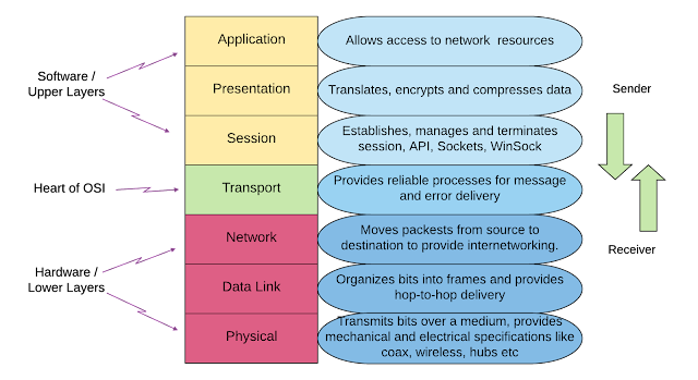
OSI LAYER MODEL Physical Layer The physical layer helps in defining the electrical and physical specifications of the data connection. This level establishes the relationship between a device and a physical transmission medium. The physical layer is not concerned with protocols or other such higher-layer items. Examples of hardware in the physical layer are network adapters, ethernet, repeaters, networking hubs, etc.   Data Link Layer The data link layer is responsible for correcting faults that may occur at the physical layer. The layer lets you specify the protocol for establishing and terminating connections between two network devices. It is an IP address comprehensible layer that aids in the definition of logical addressing so that any endpoint can be addressed and should be recognized. The layer also aids in the implementation of packet routing throughout a network. It assists you in determining the finest option path, which allows you to transfer data from one location to an...